HVAC Takeoff vs. Cost Estimating: Understanding This Service
This page covers unpriced HVAC quantity takeoff—the precise extraction of physical material quantities (ductwork linear feet, sheet metal weight, fitting counts, air terminals, and mechanical equipment counts) formatted into an auditable Bill of Materials. If your team requires complete unit pricing, shop fabrication hours, field installation labor, equipment buyouts, and bid summaries, please visit our HVAC Estimating Services page or explore general Quantity Takeoff Services.
What HVAC Quantity Takeoff Covers (CSI Division 23)
Commercial HVAC systems represent one of the most material-intensive and geometrically complex trades in building construction. Quantifying mechanical drawings requires precise cross-referencing between mechanical floor plans (M-series), roof layouts, enlarged mechanical room details, and equipment schedules to capture every duct transition, terminal device, and piping run.
ConstructQuant extracts physical quantities across all air distribution and hydronic systems, converting drawing dimensions into fabrication-ready sheet metal weights, standard pipe lengths, and verified equipment tallies:
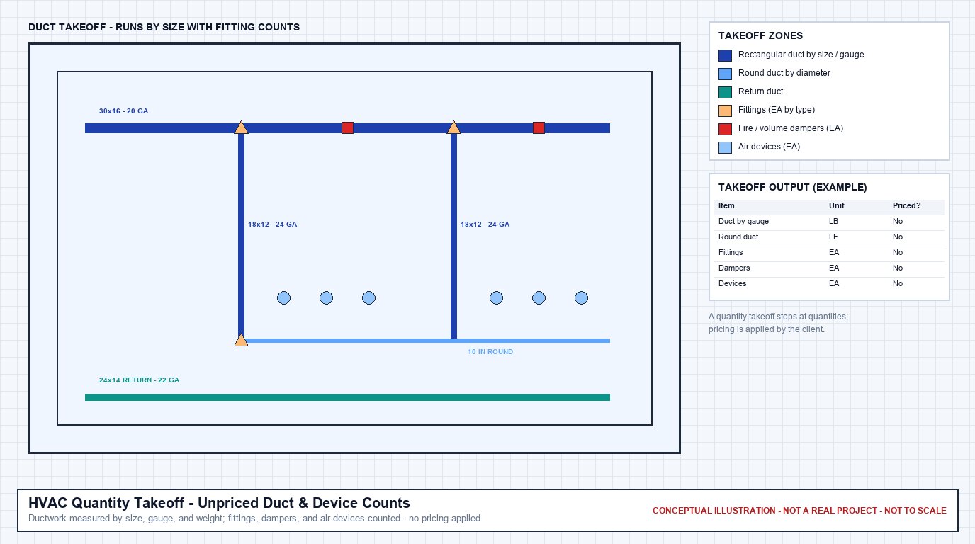
Mechanical Drawing Quantification & Sheet Metal Takeoff
Every duct run, fitting, air terminal, and mechanical equipment item is traced directly from M-series drawings and verified against mechanical schedules to produce an unpriced, auditable Bill of Materials.
1. Ductwork by System & Pressure Class
Quantified by cross-sectional dimension, shape, and SMACNA gauge thickness:
- Rectangular Ductwork: Supply air, return air, outside air, and exhaust air runs measured in linear feet (LF) and converted to sheet metal pounds (lbs).
- Spiral & Round Ductwork: High-pressure primary supply duct, exposed architectural spiral duct, and round branch runs.
- Flexible Ductwork: Insulated flex duct connections from VAV discharge to diffusers, quantified by diameter and standard run length.
2. Duct Fittings & Accessories
Itemized counts and poundage allowances for sheet metal shop fabrication:
- Transitions & Offsets: Reducers, square-to-round transitions, and directional offsets around structural steel.
- Elbows & Tees: 90-degree and 45-degree radiused and mitered elbows with turning vanes, bullhead tees, and conical taps.
- Access Doors & Test Ports: Hinged airtight duct access doors at fire dampers, coils, and control sensors.
3. Air Terminal Devices & Grilles
Reconciled item-by-item against diffuser schedule tags and ceiling reflected plans:
- Supply Diffusers: 2x2 modular cone diffusers, perforated face diffusers, and architectural linear slot diffusers.
- Return & Exhaust Grilles: Eggcrate grilles, louvered face return grilles, and door transfer grilles.
- External Louvers: Architectural intake and exhaust louvers, bird screens, and insulated blank-off panels.
4. Dampers & Airflow Control
Fire barrier penetrations and airflow balancing components quantified by dimensions:
- Fire & Smoke Dampers: Dynamic fire dampers, combination fire/smoke dampers, and motorized smoke exhaust dampers.
- Balancing Dampers: Manual volume dampers (MVD) at branch takeoffs and remote cable-operated dampers.
- Backdraft & Relief Dampers: Gravity backdraft dampers and barometric relief dampers.
5. Mechanical Plant & Terminal Equipment
Complete equipment tallies cross-checked across plans, schedules, and riser diagrams:
- Central Plant Equipment: Air Handling Units (AHUs), Rooftop Units (RTUs), chillers, cooling towers, and commercial condensing units.
- Terminal Units: VAV terminal boxes (cooling-only, electric reheat, hot water reheat) and fan coil units (FCUs).
- Ventilation Fans: Roof-mounted exhaust fans (upblast/downblast), inline cabinet fans, and stairwell pressurization fans.
6. Hydronic Piping & Thermal Insulation
Associated piping and thermal protection quantified by diameter and surface area:
- Hydronic Piping: Chilled water supply/return (CHWS/R) and heating hot water supply/return (HHWS/R) in copper and carbon steel.
- Refrigerant Lines: Suction and liquid copper line sets for VRF/VRV systems and split systems.
- Insulation: External fiberglass duct wrap (with FSK vapor retarder), internal acoustic liner (square feet), and preformed pipe insulation.
Mechanical Drawing & Schedule Reconciliation
A critical value of professional HVAC takeoff is resolving discrepancies between schematic design floor plans and mechanical equipment schedules. On commercial drawing sets, diffusers, terminal units, or exhaust fans shown on plan sheets frequently disagree with schedule quantities or CFM ratings.
Our Multi-Sheet Verification Protocol:
Confirmed Takeoff Deliverables
Every HVAC quantity takeoff project completed by ConstructQuant includes five standard, fully auditable deliverables:
1. Excel Quantity Takeoff Worksheet (Itemized BOM)
A structured, unpriced Bill of Materials organized by mechanical system (supply, return, exhaust, outside air). Details duct dimensions, standard gauges, linear footage, calculated sheet metal weight (lbs), fitting counts, and equipment tallies ready for contractor pricing import.
2. Color-Coded PDF Plan Markups
High-resolution PDF mechanical drawing sets with visual color overlays distinguishing supply air ductwork (blue), return air (yellow), exhaust air (green), hydronic piping (red/purple), and air devices with clear legend keys.
3. Excel Estimate (When Requested with Cost Modeling)
When contracted for full estimating, we provide unit material buyouts, shop fabrication labor hours, field erection labor, and equipment rental rates formatted in an open-formula workbook.
4. Bid Summary Worksheet
A consolidated executive summary categorizing total sheet metal poundage, linear footage totals by duct type, total air terminal count, and equipment schedule totals for rapid tender review.
5. Scope & Assumptions Narrative
A formal written narrative documenting drawing sheet numbers reviewed, revision issue dates, SMACNA duct construction assumptions, equipment schedule cross-references, and explicit scope exclusions.
Our 6-Step HVAC Takeoff Workflow
Every mechanical takeoff follows our standardized preconstruction quality workflow:
Plans/Documents
Intake and index all M-series drawings, specifications, reflected ceiling plans, and addenda bulletins.
Scope Review
Analyze mechanical specifications, SMACNA pressure classifications, duct materials, and equipment schedules.
Quantity Takeoff
Trace all ductwork runs, calculate sheet metal weight, enumerate fittings, air devices, and equipment counts.
Pricing (When Opted)
Apply regional trade labor rates, sheet metal fabrication hours, and equipment buyouts when estimating is requested.
QA/QC Review
QA/QC verification of duct formulas, CFM reconciliations, scale ratios, and markups.
Final Delivery
Transmit completed Excel takeoff workbooks, color-coded PDF markups, and scope narrative to your estimating team.
Frequently Asked Questions (HVAC Takeoff)
How do you calculate ductwork poundage from linear dimensions?
We determine sheet metal weight by calculating the perimeter surface area of each duct section based on drawing width and height, cross-referencing specified SMACNA pressure classes to identify the required sheet metal gauge (e.g., 24 ga, 22 ga, 20 ga, 18 ga), and applying standard galvanized steel density factors per square foot.
Does this service include pricing, or is it strictly unpriced quantities?
This service provides unpriced drawing measurements and material counts (linear feet, sheet metal pounds, air device tallies, equipment counts) in an auditable Excel Bill of Materials. If your team requires full dollar pricing including regional labor rates and markups, please request our HVAC Estimating Services.
What is your typical turnaround time for an HVAC quantity takeoff?
Turnaround is project-dependent based on the total sheet count, building square footage, system complexity, and whether hydronic piping takeoff is included. When you submit your mechanical drawings, we provide a confirmed delivery schedule in our formal service proposal.
How do you handle fire dampers and smoke dampers?
We cross-reference mechanical drawings against architectural life-safety plans to ensure every rated partition or floor slab penetration includes an appropriate fire, smoke, or combination fire/smoke damper along with required access doors and sleeves.